OPTICAL CAVITY- a set of several reflective elements forming open resonator(unlike closed volumetric resonators, used in the microwave range). For wavelengths< 0,1 см использование закрытых резонаторов, имеющих размеры d~ difficult due to small size d and large energy losses in the walls. The use of volumetric resonators with d> is also impossible due to the excitation of a large number of properties in them. oscillations that are close in frequency, as a result of which the resonance lines overlap and the resonant properties practically disappear. Thief. reflective elements do not form a closed cavity, so most of its own. oscillations are strongly damped and only a small part of them are weakly damped. As a result, the spectrum of the resulting O. r. very sparse.
O. r. - resonant system laser, which determines the spectral and mode composition of laser radiation, as well as its direction and polarization. From O. r. The filling of the active medium of the laser with the radiation field and, consequently, the radiation power removed from it and the laser efficiency depend.
The simplest O. r. is Fabry interferometer - Feather, consisting of two flat parallel mirrors. If between mirrors located at a distance d from each other, a plane wave propagates normally towards them, then as a result of its reflection from the mirrors in the space between them, standing waves (natural vibrations) are formed. The condition for their formation is where q- the number of half-waves that fit between the mirrors, called. longitudinal vibration index (usually q~ 10 4 - 10 6). Own frequency O. r. form arithmetic. progression with difference c/2d(equidistant spectrum). In fact, due to diffraction at the edges of the mirrors, the oscillation field also depends on the transverse coordinates, and the oscillations are also characterized by transverse indices T, P, which determine the number of times the field turns to 0 when transverse coordinates change. The more T And P, the higher the damping of oscillations due to radiation into space (due to diffraction of light at the edges of the mirrors). Mods with t = n = 0 name longitudinal, the rest - transverse.
Because coefficient vibration damping increases with increasing T And P faster than the frequency interval between adjacent oscillations, then the resonance curves corresponding to large T And P, overlap and the corresponding fluctuations do not appear. Coef. attenuation also depends on the number N Fresnel zones visible on the mirror dia. R from the center of another mirror located at a distance from the first d:(cm. Fresnel zone). At N~ 1 remains 1 - 2 vibrations accompanying the main. fluctuation ( q = 1).
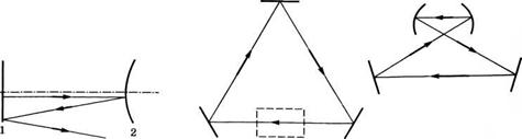
Double-mirror resonators. O. r. with flat mirrors are sensitive to deformations and distortions of the mirrors, which limits their use. O. r. are deprived of this disadvantage. with spherical mirrors (Fig. 1), in which the rays, repeatedly reflected from concave mirrors, do not go beyond the envelope surface - caustics. Since the wave field decreases rapidly outside the caustic, radiation from the spherical O. r. with caustics is much less than radiation from a flat OR. 
Rice. 1. Two-mirror resonator.
The rarefaction of the spectrum in this case is realized due to the fact that the dimensions of the caustic grow with increasing T And n. For vibrations with large T And P The caustic turns out to be located near the edge of the mirrors or is not formed at all. Spherical O. r. with caustics called stable, because the paraxial beam, when reflected, does not leave the paraxial region (Fig. 2, A). Sustainable O. r. insensitive to small displacements and distortions of mirrors, they are used with active media with low gain (10% per pass). For media with high amplification, unstable ORs are used, in which caustics cannot form; a beam passing near the resonator axis at a small angle to it, after reflections, moves away from the axis indefinitely. In Fig. 2( b) the stability diagram of the O. R. is given. at decomposition relationships between radii R 1 and R 2 mirrors and distance d between them. Unshaded areas correspond to the presence of caustics, shaded areas correspond to their absence. The points corresponding to the resonator with flat (P) and concentric (C) mirrors lie on the border of the shaded areas. On the border between stable and unstable O. r. the confocal OR is also located. ( R 1 = R 2 = d). Of the stable O. r. max. semi-confocal is often used ( R 1= x R 2 = 2d), from unstable - telescopic O. r. ( R 1+ R 2 = 2d). Radiation losses in unstable ORs. for vibrations of higher types is much greater than for basic ones. fluctuations. This makes it possible to achieve single-mode laser generation and the associated high directivity of radiation.

Rice. 2. Formation of caustics ( A) and stability diagram of two-mirror resonators ( b): plus signs indicate areas of stability; minus - areas of instability; solid lines are the boundaries of these areas; P - resonator with flat mirrors; Conf. - confocal resonator; K - concentric resonator; dotted line - line of telescopic resonators.
Theory. Electrical distribution fields E sustainable O. r. in a plane perpendicular to the axis of the O. r. ( z), described by the expression
Here E 0- coefficient that determines the amplitude of the field; N t, p- Hermite polynomials (see. Orthogonal polynomials) t th and n th degrees: H 0 (x) = 1, N 1 (x) = 2x, N 2 (x) = 4x 2 - 2, N 3 (x) = 8x 3 - 12x; W- transverse radius of the longitudinal mode (at a distance from the O.R. axis equal to W, the energy density of the longitudinal mode decreases in e once). Addiction W(z) has the form
![]()
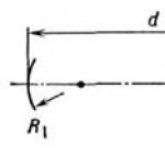
where a z is measured from the so-called. waist of the longitudinal mode, i.e. from the point on the resonator axis where its radius is at its maximum. value equal to W 0(Fig. 2, A). Distance from the banner to the mirror R 1
![]()
radius of the longitudinal mode in the waist
Frequency spectrum of a two-mirror O. r. is given by the condition

The field distribution on the mirror is shown in Fig. 3. Because the frequency spectrum of a two-mirror O. r. degenerate (depends only on the sum t + n, but not from each of the indexes separately), then E(x,y)may differ from (1). The specific type of distribution depends on the weak disturbances from diaphragms or other objects in the area occupied by the beam. In particular, with axial symmetry, field distributions are possible (Fig. 4), described in cylindrical terms. coordinates ( r,, z) expression
Here l,p- fluctuation indices that determine the number of times the field turns to 0 when changing r And W(z)- radius of the longitudinal mode; - generalized Laguerre polynomial:
Spectrum O. r. with axial symmetry is determined by relation (2), where ( T + P+ 1) should be replaced with ( 2p + l+ 1).

Rice. 3. Field distribution on the mirror with rectangular symmetry.
Rice. 4. Field distribution on the mirror with axial symmetry; * corresponds to the field distribution when two orthogonally polarized modes are added.
Composite resonator. In addition to the mirrors O. r. often contains the so-called active elements (plates, lenses, etc.). Composite O. r. can operate in two modes depending on whether radiation reflected from intermediate surfaces is used or lost. If reflected radiation is used, then O. r. called agreed upon. Each part of the agreed-upon operational structure, enclosed between two adjacent interfaces, can be considered as a separate part. resonator, and the transverse modes of these resonators are selected so that they coincide at the interfaces. The matching condition (Fig. 5) has the form

Agreed O. r. has a non-equidistant spectrum and can be used to rarefy the longitudinal spectrum of OR. (see below).
An important problem in the case of composite O. r. is eff. filling the laser active medium with the field of the selected mode. If the composite O. r. has an axis or plane of symmetry, then the longitudinal mode (like that of a two-mirror O, r.) is a Gaussian beam (see. Quasi-optics). Its passage through optical fiber. elements are described by the matrices of these elements (see Matrix methods in optics), and passage through the O. r. is described by a matrix, which is the product of the matrices of its constituent optical elements. elements. In this case, the complex parameter of the Gaussian beam q determined by equation
Cq 2 + (D - A)q - B = 0.
Coef. A, B, C, D form a matrix of O. r. This equation, as well as the relations R= -l, = [kIm(1 /q)] -1 make it possible to determine the transverse radius of the beam and the radius of curvature of the wave front R in any section of the resonator.
Selection of longitudinal modes. To rarefy (select) longitudinal modes that have the same transverse field distribution but differ in frequency, resonators containing dispersive elements (prisms, diffraction gratings, interferometers, etc.) are used. In particular, additive is used as a dispersion element. O. r. associated with the main one and forming the so-called. equivalent mirror, coefficient reflections r depends on frequency v. To remove one of the longitudinal modes from the spectrum, max. A linear three-mirror O.R. is suitable. (Fig. 6, A), to highlight one longitudinal mode in the spectrum - a Fox-Smith resonator (Fig. 6, b) and T-shaped (Fig. 6, V). In some cases, O. r. is convenient. Michelson (Fig. 6, G).

Rice. 6. Various types of coupled resonators (I) and the dependence of the reflection coefficient of the equivalent mirror on frequency v(II).
Dye lasers use a combination of diffraction patterns. lattice and Fabry-Perot interferometer (Fig. 7). In this case, the interferometer selects one longitudinal mode, and the grating prevents generation on other orders of the interferometer. Lenses L 1 and L 2, forming the so-called. telescope, they match a narrow beam passing through the active medium A with a wide beam incident on the interferometer and the grating. The active medium in such an OR. also plays the role of a diaphragm, highlighting the main. transverse mode. Such O. r. made it possible to create single-frequency tunable over a wide range dye lasers.

Rice. 7. A resonator containing dispersive elements (used in dye lasers). A - cuvette with active medium; Z - opaque or partially transparent mirror; I - Fabry - Perot interferometer; D - diffraction grating.
Selection of transverse modes is based on the difference in the distribution of fields of transverse modes with different T And P. Because usually you need to highlight the main. fashion, edge has min. angle, divergence, Gaussian distribution and min. length in the transverse direction, then diaphragm of the beam inside the OR is applied. The radius of the diaphragm should be approximately equal to the transverse radius of the mode following the main one. In this case, the losses of all modes except the main one greatly increase.
When selecting transverse modes, it is necessary that the remaining unity. fashion effectively filled the active environment. Therefore, the boundaries of stability zones are important (Fig. 2, 6
), where the transverse dimensions of the modes increase: 1) the radius of the mode increases throughout the entire volume if the distance d between the mirrors is constant, and the radii of the angle of the mirrors R l And R 2(at the same time, the sensitivity of the resonator to misalignments greatly increases); 2) the mode radius increases on the 1st mirror and decreases on the 2nd if dR 1(R 2
>R 1); 3) the mode radius increases on the 2nd mirror and decreases on the 1st if d R 2 ; 4) the mode radius increases on both mirrors and decreases in the region of their centers of curvature if d (R 1 + R 2).
If it is necessary to isolate any of the highest mode, a thin scattering filament is placed on the zero line of the field distribution of this mode, which has no effect on the selected mode and suppresses other modes that do not turn to 0 on this line.
Resonators with anisotropic elements. The polarization of laser radiation is determined by the so-called. anisotropic elements found in the O. river. Such elements are birefringent plates, polarizers,substances having optical activity, etc., as well as Brewster plates and dielectric. mirrors with oblique incidence of radiation on them. Polarization is determined using the Jones matrix method. At the same time, polarization matrix of the entire O. r. is the product of the matrices of its constituent elements, arranged in the order in which radiation passes through these elements starting from the place where it is necessary to determine the state of polarization. Own polarization vectors matrices are Jones vectors E(E x, E y) fields generated in O. R. The degree of polarization e and the direction of ch. the axes of the polarization ellipse a are determined by the relations
![]()
Where R = |E x | / |E y |,= arcig( E y/E x).
Own modules The values of the Jones matrix determine the OR losses caused by the polarizers, and the phases of the own. values - polarization corrections to the frequencies of the corresponding modes. By selecting anisotropic elements, the required state of polarization can be achieved. Considering that anisotropic elements usually have noticeable dispersion, they can also be used to rarefy the longitudinal spectrum.
Ring resonators. Range of properties frequencies of a ring OR, formed by three identical spherical. radius mirrors R, located at the vertices of an equilateral triangle with side A(Fig. 8), is determined by the relation


Rice. 8. Ring optical resonators.
The mode waists are located at the midpoints of the sides of the triangle; The transverse extents of the modes in the waist region in the plane of the axial contour are equal to:

If the resonator has only one spherical mirror and two flat ones (Fig. 8,6) , then its spectrum is determined by the relation

The transverse extents of the modes in the region of the waist, the edges are located in the middle of the side of the triangle opposite the spherical one. mirror in the plane of the resonator are equal to:
Optical system that forms the O. r. with a non-flat contour, e.g. system of 4 mirrors located at the vertices of the tetrahedron (Fig. 8, V), is characterized by the fact that the image of a particular object, constructed using this system, is rotated relative to the object itself by a certain angle characteristic of this system. For a tetrahedron, this angle is equal to where are the angles between adjacent planes of incidence of rays on the mirrors (faces of the tetrahedron), which are measured so that the tetrahedron lies inside the angle. Longitudinal mode O. r. with a non-planar contour is a beam, in which Ch. axes elliptical amplitude distribution are rotated at a certain angle relative to the gl. wavefront curvature lines. Due to this, the amplitude distribution as the beam propagates in free space undergoes a rotation, which compensates for the rotation caused by the volumetric arrangement of the mirrors. Ring O. r. with a non-flat contour are used, for example, in laser gyroscopes. They make it possible, in particular, to get rid of the anisotropy inherent in ring ORs. with a flat outline.
Unstable resonators have high radiation losses to the outside. space (see above). Losses increase with increasing T And P, thanks to this, unstable O. r. provide single-mode (according to T And P)generation. The advantage of unstable O. r. is the large transverse extent of the main. modes, as a result of which they can be used with active media of large cross-section. Energy is removed from an unstable orbital system, as a rule, not through mirrors, as in stable orbital reactors, but beyond the edges of one of the mirrors. In unstable O. r. a significant (negative) role is played by the wave reflected from the edge of the mirror and converging towards the axis of the optical system. To reduce such reflection, smoothing of the edge of the mirror is used, giving it a star-shaped shape, rounding the edges, etc.
Basic fashion of unstable O. r. formed by two spherical waves propagating between the mirrors towards each other. In the case of telescopic unstable O. r. (Fig. 9) one of the waves may be flat. Center spherical waves lies in the distance x = R 2 /2 behind a convex mirror with a radius of curvature R 2. The concave mirror must have a radius of curvature | R 1 | = R 2 + 2d (R l< 0). При достаточно больших
поперечных размерах 1-го зеркала пучок излучения кольцевой формы выводится
в сторону выпуклого зеркала с волновым фронтом, близким к плоскому.
Unstable O. r. with rotation, the fields are formed by a defocusing system of mirrors located at the vertices of a non-planar polygon. However, most Important are the optical lines formed by two dihedral corner reflectors (Fig. 10), the edges of which are turned at an angle relative to each other. If one or several. the faces of the reflectors are convex, then the O. r. unstable.

Rice. 9. Unstable telescopic resonator. 
Rice. 10. Linear resonator with field rotation, formed by corner reflectors.
When the field completely bypasses such a resonator, it experiences a rotation through an angle. An advantage of an unstable OR. with field rotation, it is possible to output radiation in the form not of an annular beam, as in a conventional unstable OR, but of a simply connected compact beam (Fig. 11). 
Rice. 11. Energy output in the form of a compact simply connected beam from an unstable resonator with field rotation by AC- edge of the corner reflector of the mirror, near which the radiation beam is output (shaded), NN"- edge of the same mirror, GG" - edge of the second corner reflector.
Lit.: Vainshtein L.A., Open resonators and open waveguides, M., 1966; Ananyev Yu. A., Optical resonators and the problem of laser radiation divergence, M., 1979; Handbook of Lasers, trans. from English, ed. A. M Prokhorova, vol. 2, M., 1978, ch. 22, 23; Karlov N.V., Lectures on quantum electronics, 2nd ed., M., 1988.
is determined by comparing the radiation patterns of a real antenna and its continuous analogue in the range of angles of interest to us.
The article describes a new version of the integrated phased array antenna - slot IPAR. This antenna is a dual analogue of the dipole IFAR proposed earlier by the staff of the Department of Radiophysics of St. Petersburg State Polytechnic University.
In a slot IPAR, unlike a dipole one, a closed ferrite-dielectric waveguide is used, which gives this antenna some advantages. Based on the continuous model, the main parameters of the antenna were found: gain, efficiency, radiation pattern. It is shown that for practically interesting cases the continuous model of this antenna gives accurate results
bibliography
1. Zaitsev, E.F. MM-wave Integrated Phased Arrays with Ferrite Control [Text] /E.F. Zaitsev, Yu.P. Yavon, Yu.A. Komarov // IEEE Transactions on Antennas and Propagation. -March, 1994. -Vol. 42. -No. 3. -P. 1362-1368.
2. Zaitsev, E.F. New electrically scanning antennas in the millimeter wave range [Text] / E.F. Zaitsev, A.B. Guskov, A.S. Cherepanov // Izv. universities in Russia. Ser. Radioelectronics. -2003. -No. 4. -S. 3-12.
3. Zaitsev, E.F. Analysis of antennas with sequential excitation of the aperture and electrical scanning based on controlled magnetogyrotropic structures [Text] / E.F. Zaitsev, A.N. Fedotov, Yu.P. Yavon // Dep. in VINITI, No. 1120-B88.
4. Cherepanov, A.S. Elementary theory of integral phased array antennas [Text] / A.S. Cherepanov, E.F. Zaitsev, A.B. Guskov. -SPb.: SPbSTU, 1999 // Dep. in VINITI, No. 3849-B99.
D.V. Dikiy, A.S. Cherepanov, V.K. Nuzhin
dual-band antenna on ring resonators
traveling wave
In some cases, it is convenient to use a traveling wave ring antenna in microwaves. This is explained by the increased interest in many areas of radio engineering (radiolocation, radio telemetry, radio control, space radio communications, etc.) in antennas with elliptical or rotating polarization.
If in a conducting ring (travelling wave resonator - RBV), the length of which is a multiple of the length
waves X (diameter B = -, where w = 1, 2, 3, ...),
excite a current that varies according to the law of a traveling wave with a constant amplitude 10, i.e., determined by the equation 1 = 10e-k5, where 10 is the current at the initial point on the ring, having coordinates x = R, y = 0, z = 0; 5 - arc length from the initial one
points to element M; 5 = I<р"; к =- (рис. 1),
then the created electric field will have two components: meridional E9 and azimuthal Eph. Moreover, both components are shifted
relative to each other in phase by 90°. Consequently, we obtain a field of rotating (elliptical) polarization.
In this case, in the plane of the ring (9 = 90 °), the meridional component of the field E9 becomes zero and only the azimuthal component Ef remains, i.e., a linearly polarized field is obtained. At an acute angle to the ring axis, the field has an elliptical polarization. If in length
the rings are laid in one wave (w =-= 1),
Along the axis of the ring, a circularly polarized field is obtained. When the length of the ring is equal to two, three, etc. waves (w = 2, 3, ...), there is no radiation along the axis of the ring.
Antenna design on RBV
The use of ring elements as elementary vibrators provides a number of operational and design advantages compared to linear vibrators: the presence
Rice. 1. Ring emitter - traveling wave resonator
elliptical polarization using a minimum number of vibrators, the possibility of implementation in microstrip design.
A traveling wave ring resonator is a long line rolled into a ring. The resonator is excited using a directional coupler on connected lines (Fig. 2).
For an ideal symmetric directional coupler, the scattering matrix has the following form:
w^S12 = w^5 +-.
For the normalized waves indicated in Fig. 1, the following relations hold:
a2 = b4e-(a+m)"", b3 = ^ + 5.2 a4, b1 = 512 a2 + 512 a3, b4 = 513a2 + 512 a3, (3) b2 = a1 + 513a4, a4 = b2eAa-+ m)1", where (a + ym) is the wave propagation constant in the ring (m = -); I" is the length of free X
section of the ring; X is the wavelength.
In the presence of a matched load at the output, a3 = 0, and from the first two equations it follows:
a2 = a2 513e-(a+^y.
Since 813e-(a+m)1" * 0, then a2 = 0, and taking into account (3):
b = a2 = b 4 = 0.
1 - 513e-<а+м)1"
Rice. 2. Ring emitter power supply circuit
Analysis of equations (4), (5) shows that at the frequency determined from the equality
Arg S13 + ml" = 2nn, n - integer (6)
and provided that the attenuation in the ring obeys the relation
There is a ring resonance in the system. In this case, the amplitude of the b2 wave in the ring is enhanced compared to ax and amounts to
For the coupler, taking into account the unitarity of the matrix S, |S13| + |S121 = 1, and condition (7) becomes the equality
1 - e~2al" = |S12|2. (9)
Then |b2| = Ш/|S12|, according to (5) taking into account (2) b3 = 0, that is, all the power is absorbed in the ring.
If the traveling wave resonator (TWR) is made on an open line of the stripline type, then the radiation losses will be useful, and thus we will obtain an elliptical polarization antenna.
In the case of a high-quality resonator (al"<< 1, |S121« 11), когда |b21 « |aj , излучением из области петли связи можно пренебречь, и с учетом слабого затухания волны b2 по кольцу поляризация излученного в осевом направлении поля будет практически круговой. В случае слабой связи - arg S13 = ml" , где Г - длина участка
communications. Thus, in accordance with (6), the total length of the ring I = V + Г at the resonance frequency is 2pp/m = nX.
The parameters of interest for the RBV irradiator are:
1) the power level passed from shoulder 1 to shoulder 3 BUT, which determines the notch;
2) Efficiency, which, in the absence of ohmic losses in the elements of the feed, is the difference between the incident power into arm 1, reflected from arm 1 and transmitted to arm 3. It coincides with the power emitted by the feed, related to the incident power.
Qualitative view of the system's frequency response according to efficiency R
P = -- (P - radiated power) and according to rez-P
losses from R
losses with tion U = shown in Fig. 3 b, curve 3. As well as
in any resonant system, the width of the resonance curve is greater, the greater the losses in it (in this case, these are radiation losses).
Increasing the bandwidth requires increasing the attenuation in the ring (which can be achieved by increasing the width of the ring and its height above the screen) and, accordingly, increasing the coupling coefficient 512 of the directional coupler. Both entail a deterioration in the symmetry of the radiation pattern and deteriorate the quality of circular polarization. Therefore, good electrodynamic (in particular, polarization) characteristics in such a design of the radiating structure on the RBV can be achieved only with a relatively narrow frequency band.
However, if several ring RBVs are connected by cascaded directional couplers (Fig. 3 a), then in such a system (as in any multi-resonator system) the dispersive effect can be obtained.
Rice. 3. Multi-resonator system based on RBV (a) and an approximate view of the frequency response in terms of rejection y and efficiency p (b)
broadening the bandwidth and improving the rectangularity of the frequency response (Fig. 3 b)
In this case, depending on the values of the coupling coefficients of 512 directional couplers, both a multi-humped (curve 1), for example Chebyshev, and the most flat form of the frequency response (Butterworth, curve 2) can be realized. The rejection band, with a fairly strictly specified tolerance on its quality, turns out to be larger than in the case of a single-section filter. Note that only the upper ring is emitting, the other two are idle, have no losses and do not take part in the formation of the radiation field of the structure.
However, multicavity as such does not affect the radiation field of the structure. To improve it (mainly the quality of polarization), it is necessary to distribute the coupling of the radiating ring, and in such a way that the ring remains radiating.
If two electrodynamically unconnected lines are connected to each other by several coupling elements that weakly disturb the field in the lines, placed at a certain interval, then in a certain frequency band the effect of directional coupling between the lines may occur, even in the absence of directionality of the coupling elements themselves, due to the interference of incident and reflected waves The best effect (in terms of broadband) is achieved when the interval between communication elements is equal.
also with another interval, it is only important that it is not a multiple of half the wavelength.
The radiation pattern of the ring (Fig. 4) with a traveling current wave of constant amplitude in the far zone has the form: , ni
H = [ L-1 (n sin 9) - Jn+l (n sin 0)], 4r
K | = -JL[ Jn-1 (n sin 0) + Jn+1 (n sin 0)] cos 0, 4r°
where I° is the current amplitude; r° - distance from the phase center to the observation point; Jn l ,Jn+l - Bessel functions of corresponding orders; H0, Hf - spherical components of the magnetic field vector.
Phase shift between H0 and Нф for any n
n and 0 is -. Analysis of expressions (1°) shows that the resonant ring radiates in the axial direction 0 = ° only at n = 1 (I = X).
If the ring is located above a large flat conducting screen, then, taking into account the mirror image for l = X, the radiation pattern will look like this:
Н0 Jn-,(n sin 0) -
Jn+l(n sin 0)]sin I 2п - cos 0
H 0.2 0.4 0.6 0.8 1.0 Pmax Fig. 4. Radiation pattern of the feed on the RBV for the main and cross polarizations where b is the height of the radiating ring above the screen. The calculated radiation pattern of the antenna on the RBV for the main and cross polarizations at a ring height above the screen of 0.01 X is shown in Fig. 4. Design features of a dual-band RBV irradiator The RBV antenna has the useful property that it allows you to combine antennas of different ranges by simply inserting them into each other. In this work, we investigated a dual-band antenna intended for use as a radio telescope feed. A dual-range RBV irradiator consists of two RBV irradiators inserted into one another for a range of 3.5 and 13 cm. The average diameter of the emitting ring for the 3.5 cm range is 1.1 cm, and for the 13 cm range - 4.1 cm. With such ratios of ring diameters, problems associated with combining two irradiators do not arise. The required bandwidths for the 3.5 and 13 cm bands are 10 and 15%, respectively. Such bands are achieved only in a multicavity design with at least two resonators and using quarter-wave coupling between the resonators. In this case, the linear size of the irradiators will be about 3.5/4-2 = 2 cm 13/4-2 = 8 cm, respectively. In this case, it is necessary to additionally take into account the length of the supply cables, the height of the emitting ring and the radome of the longest wavelength irradiator. You can preliminary estimate your Rice. 5. Photo of the antenna model cell of a dual-band feed is 13-15 cm. The maximum diameter will be 1.5-2 wavelengths of the longest wave feed. Experimental studies of the antenna layout were carried out. A photograph of the antenna under study is shown in Fig. 5. Antenna noise temperature measurement The following technique was used to measure noise temperature. A highly sensitive centimeter range receiver (converter) with its own noise temperature of 17K was used as a measuring device. At the receiver output, the intensity of the noise signal was monitored using a measuring device. A reference antenna (corrugated horn) was initially placed at the input of the receiving device. 1) calibration measurement of the reference antenna at room antenna temperature (T = 300 K) and at liquid nitrogen temperature (K = 77 K); 2). 3) the reference antenna was replaced by the one under study and the noise intensity was measured when the antenna was oriented towards the sky and towards the ground. Based on the results of these measurements, an estimate of the noise temperature of the antenna under study was obtained, which turned out to be approximately 40 °K. In Fig. Figure 6 shows the experimentally measured coefficients |531| (transmission coefficient from antenna input 1 to input 3 - Fig. 2) for both ranges. Low value |531| means intense radiation into space. It can be seen that it was possible to obtain effective energy radiation in the given frequency ranges. Circularly polarized antennas, built on the basis of a traveling wave ring resonator, have a number of advantages, such as simplicity and elegance of design, compactness, high gain value with low suspension height (low silhouette); the possibility of combining several resonators Frequency, GHz 7.5 8 8.5 Frequency, GHz Rice. 6. Energy rejection in the dual-band antenna model in the range of 13.5 cm (a) and 3.5 cm (b) tori in the form of concentric rings; simple separation of right- and left-handed polarization fields into two independent channels, which is very valuable, for example, in radio astronomy equipment, where such separation is necessary to determine the magnetic field of the source. The disadvantage of the RBV antenna design described above is the difficulty of implementing a wide band while maintaining good radiation characteristics. A certain limitation of the RBV design is also the uneven shielding effect of the coupling loop, which leads to deterioration of the radiation characteristics. bibliography 1. Bogod, V.M. Multi-wave feed on traveling wave resonators with a single phase center for use in radio astronomy [Text] / V.M. Bogod, V.N. Dikiy, Ya.V. Korolkov [and others] // Izv. SAO. -1980. -T. 17. -S. 124-130 2. Dikiy, D.V. Method for exciting a traveling current wave in a ring frame [Text] / D.V. Wild. -SPb.: SPbSPU, 2004. -Deposited in VINITI 03/11/2004. -No. 426-B2004. 3. Dikiy, D.V. Increasing the directionality of the emitter on traveling wave resonators by segmenting the radiating element [Text] / D.V. Wild. -SPb.: SPbSPU, 2004. -Dep. in VINITI 03/11/2004. -No. 425-B2004. 4. Dikiy, D.V. Cryostatic multi-frequency irradiator based on traveling wave resonators [Text] / D.V. Dikiy, V.K. Nuzhin, A.S. Cherepanov // All-Russian. Radio Astronomy Conf. Radio telescopes, equipment and methods of radio astronomy. - St. Petersburg, October 17-21. 2011. -S. 74-75. UDC 621.396.663 G.S. Sharygin, D.V. Dubinin optimization of the structure of a ring antenna array used to determine the angles of arrival of plane electromagnetic waves using the phase method Determination of angles of arrival (direction finding) - location observation. In most cases, one of the central tasks when creating tea systems, the problem of direction finding is solved using radio navigation, active and passive radio antennas. However, different methods The invention relates to laser technology and is intended for use primarily in a gas laser. The technical result of the invention is the creation of an optical resonator, which allows minimizing the weight and size characteristics of gas lasers, and increasing the manufacturability of their manufacture. The ring optical resonator contains a system of mirrors that form the optical axis in the form of a closed broken line. The mirrors of the system are installed along the surfaces of an annular cavity formed by cylindrical coaxial surfaces. In this case, the mirrors are located relative to each other in such a way that they form, in a section perpendicular to the axis of the coaxial cylindrical surfaces, an optical axis in the form of a closed broken line, the segments of which intersect the annular cavity. 2 ill. The invention relates to laser technology and is intended for use primarily in a gas laser. Linear optical resonators with mirrors located on one straight line, which is the common optical axis of the mirrors (resonator axis) (Tarasov L.V. Lasers and their application. "Radio and Communications", 1983), have become widely used in the design of technological lasers. The disadvantage of the mentioned resonators is the increased weight and size characteristics of laser systems made on their basis. This is due to the fact that the laser flow channels, intended for pumping the gaseous active medium, are box-shaped with a rectangular cross-section. The manufacturability of such a design is low, since special equipment is required for high-precision processing of rectangular channels. Known ring optical resonators provide circulation of the light flux along a certain closed circuit. This is achieved by using a system of three (or more) mirrors suitably positioned relative to each other. (Physical encyclopedic dictionary. M.: Soviet Encyclopedia, 1983, p. 500). The disadvantage of the known ring resonators is that their use does not achieve the necessary reduction in the parameters of the weight and size characteristics of the laser installation. The objective of the invention is to eliminate the shortcomings of the known ring optical resonator and create a ring resonator that allows minimizing the weight and size characteristics of gas lasers and increasing the manufacturability of their manufacture. The task is achieved by the fact that in the proposed ring optical resonator containing a system of mirrors forming the optical axis in the form of a closed broken line, the mirrors of the system are installed along the surfaces of the annular cavity formed by cylindrical coaxial surfaces, while the mirrors are located relative to each other so that they form section perpendicular to the axis of coaxial cylindrical surfaces, the optical axis in the form of a closed broken line, segments of which intersect the annular cavity. Improve the operational properties of the laser system by minimizing its weight and size characteristics; Reduce the cost of manufacturing a laser system by increasing its manufacturability. The essence of the invention is illustrated in Fig. 1, Fig. 2, which shows projections of the design diagram of a ring optical resonator (hereinafter referred to as the “resonator”). Figure 1 shows a longitudinal section BB with an image of the structural elements of the resonator. Figure 2 shows (on an enlarged scale) cross section A-A depicting the structural elements of the resonator. The positions are indicated: 1 - mirror located along the outer cylindrical surface; 2 - mirror located along the inner cylindrical surface; 3 - system of mirrors 1, 2; 4 - optical axis of the mirror system; 5, 6 - coaxial cylindrical surfaces - external and internal; 7 - annular cavity; 8 - axis of coaxial cylindrical surfaces; 9 - output window of the laser light beam; 10 - emitting hole(s); 11 - segment of the optical axis - direction of initial excitation of the active medium; 12 - hole for input of photons of initial excitation of the active medium. The arrows “Input” and “Output” in Fig. 1 show the direction of flow of the active medium through the annular cavity 7 of the resonator. The resonator, Figs. 1, 2, is an integral part of the laser and is designed to excite electromagnetic waves in the optical range (the remaining parts of the laser are not shown in Figs. 1, 2). The resonator is a system (set) of 3 mirrors 1, 2 located along the surfaces of the annular cavity 7 formed by coaxial cylindrical surfaces 5 and 6. Mirrors 1, 2 of system 3 are located relative to each other so that they form in sections A (Fig. 2) , perpendicular to the axis 8 of the coaxial cylinders 5 and 6, the optical axis 4 in the form of a closed broken line, the segments of which intersect the annular cavity 7. In a real gas laser design, the walls of the laser housing are located along the surfaces of the annular cavity 7, forming a channel. A system of mirrors 3 is installed in the channel, along which gas is pumped, which is the active medium with the inversion state achieved (the device for achieving the inversion state of the active medium is not considered here). The resonator works as follows. To switch the resonator into the stationary lasing mode, an initial excitation (push) is created in the active medium, for example, in the form of photons emitted through hole 12 along segment 11 of the optical axis of the resonator (the device for forming the initial excitation of the active medium is not considered here). The mentioned photons, repeatedly reflected by mirrors 1, 2 of system 3, again and again pass through the active medium along a closed broken line of the optical axis 4, causing an increasing avalanche of acts of stimulated emission. The process is accompanied by energy losses. The losses consist of internal losses (for example, due to absorption and scattering of light in the active medium, mirrors and other elements of the laser) and energy radiation losses through the output window 9. The output window is made in the form of a translucent mirror or in the form of a mirror with a emitting hole (holes) ) 10. During continuous lasing, the avalanche-like increase in the power of stimulated emission is limited by nonlinear processes in the active medium and the power of the pump source. As a result of these restrictions, the increase in wave intensity stops. The operation of the resonator (providing laser radiation) continues during the time of maintaining pumping of the active medium from an external energy source. Mirrors of system 3 can be made either in the form of a set of individual elements 1 (Fig. 2), or in the form of a solid part - a ring, the edges of which form mirrors 2 (Fig. 2). If it is necessary to change the spatial characteristics of the laser beam, well-known technical means are used, which are not discussed here. The proposed cavity design can also be used in solid-state lasers. The combination of the above essential features in the implementation of the proposed invention makes it possible to obtain the following technical results: Reduce the weight and size characteristics of a gas laser by making its flow part axisymmetric instead of box-shaped. Reducing weight and size characteristics is especially important for lasers intended for placement on vehicles; Reduce the cost of laser manufacturing by increasing its manufacturability by replacing the box-shaped resonator housing parts with axisymmetric ones. A ring optical resonator containing a system of mirrors forming an optical axis in the form of a closed broken line, characterized in that the mirrors of the system are installed along the surfaces of the annular cavity formed by cylindrical coaxial surfaces, while the mirrors are located relative to each other so that they form in a section perpendicular to the axis coaxial cylindrical surfaces, the optical axis in the form of a closed broken line, the segments of which intersect the annular cavity. Ring resonator- an optical resonator in which light propagates along a closed path in one direction. Volumetric ring resonators consist of three or more mirrors oriented so that light is sequentially reflected from each of them, completing a full rotation. Ring resonators find widespread use in laser gyroscopes and lasers. Fiber lasers use special designs of fiber ring resonators, usually in the form of an optical fiber closed in a ring with WDM couplers for inputting pump radiation and outputting generated radiation. An extremely important type of laser resonator is the ring resonator, in which the optical path of the rays has a ring (Fig. 5.4a) or a more complex trajectory, such as that shown in Fig. 5.46 “folded” trajectory. In both cases, the resonant frequencies of the ring resonator can be determined by imposing the condition that the total phase change along the ring path in Fig. 5.4a or along a closed path in Fig. 5.46 (shown by solid lines) must be a multiple of 2l. In this case, it is easy to obtain the relation for resonant frequencies: Optical diode Where Lp is the perimeter of the ring or the length of the closed trajectory in Fig. 5.46, and n is an integer. Note that the arrows showing the directions of the rays in Fig. 5.4 can, generally speaking, be turned in the opposite direction. This means that, for example, in Fig. 5.4a radiation can propagate both clockwise and counterclockwise. Thus, in the general case, a standing wave is formed in a ring resonator. However, you can use some device that provides unidirectional propagation of radiation, for example, only from right to left in Fig. 5.4a (optical diode, see section 7.8.2.2 for more details). Then only a wave traveling clockwise will exist in the resonator. Thus, the concepts of resonator mode and resonant frequency are associated not only with standing waves. Note that ring resonators can also have either stable (as in Fig. 5.4) or unstable configurations. Example 5.1. Number of modes in closed and open resonators. Let us consider a He-H laser generating at a wavelength X = 633 nm, with a Doppler amplification line contour of width Ау5 = 1.7 109 Hz. Let us set the length of the resonator equal to b = 50 cm and first consider an open resonator. In accordance with (5.1.3), the number of longitudinal modes entering the amplification circuit is equal to Toren = 2bAc/c = 6. Let us now assume that the resonator is limited by a cylindrical side surface with a diameter of 2a = 3 mm. In accordance with (2.2.16), the number of modes of such a closed resonator falling into the amplification circuit of width Ауо is equal to MCІ08Є(І = 87іу2^Ауо / с3, where V = с/Х is the laser frequency, and V = na2b is the volume of the resonator. Using the given expressions and selected parameter values, it is easy to obtain that Lis1tea = (2na / X)2 Liorep g 1.2 109 mod. Metal engraving is carried out using professional equipment. Highly detailed engraving is used to decorate gifts and memorabilia. This section provides a brief description of the coherent properties of light that is emitted by a conventional lamp (incandescent or gas-filled lamp). Since light in this case is due to the spontaneous emission of many atoms, essentially... As a result of collisions of particles with electrons in the volume of an electric discharge, electrons and ions are constantly formed. Impact ionization is carried out by the hot electrons present in the discharge, i.e. those whose energy is greater...Drawings for RF patent 2388123
CLAIM
see also
Write a review about the article "Ring resonator"
Literature
Links
Excerpt characterizing the Ring resonator
“Yes, a nice wallet... Yes... yes...” he said and suddenly turned pale. “Look, young man,” he added.
Rostov took the wallet in his hands and looked at it, and at the money that was in it, and at Telyanin. The lieutenant looked around, as was his habit, and suddenly seemed to become very cheerful.
“If we’re in Vienna, I’ll leave everything there, but now there’s nowhere to put it in these crappy little towns,” he said. - Well, come on, young man, I’ll go.
Rostov was silent.
- What about you? Should I have breakfast too? “They feed me decently,” Telyanin continued. - Come on.
He reached out and grabbed the wallet. Rostov released him. Telyanin took the wallet and began to put it in the pocket of his leggings, and his eyebrows rose casually, and his mouth opened slightly, as if he was saying: “yes, yes, I’m putting my wallet in my pocket, and it’s very simple, and no one cares about it.” .
- Well, what, young man? - he said, sighing and looking into Rostov’s eyes from under raised eyebrows. Some kind of light from the eyes, with the speed of an electric spark, ran from Telyanin’s eyes to Rostov’s eyes and back, back and back, all in an instant.
“Come here,” Rostov said, grabbing Telyanin by the hand. He almost dragged him to the window. “This is Denisov’s money, you took it...” he whispered in his ear.
– What?... What?... How dare you? What?...” said Telyanin.
But these words sounded like a plaintive, desperate cry and a plea for forgiveness. As soon as Rostov heard this sound of the voice, a huge stone of doubt fell from his soul. He felt joy and at the same moment he felt sorry for the unfortunate man standing in front of him; but it was necessary to complete the work begun.
“People here, God knows what they might think,” Telyanin muttered, grabbing his cap and heading into a small empty room, “we need to explain ourselves...
“I know this, and I will prove it,” said Rostov.
- I…
Telyanin's frightened, pale face began to tremble with all its muscles; the eyes were still running, but somewhere below, not rising to Rostov’s face, sobs were heard.
“Count!... don’t ruin the young man... this poor money, take it...” He threw it on the table. – My father is an old man, my mother!...
Rostov took the money, avoiding Telyanin’s gaze, and, without saying a word, left the room. But he stopped at the door and turned back. “My God,” he said with tears in his eyes, “how could you do this?”